• We have updated our Community Code of Conduct. Please read through the new rules for the forum that are an integral part of Paradox Interactive’s User Agreement.
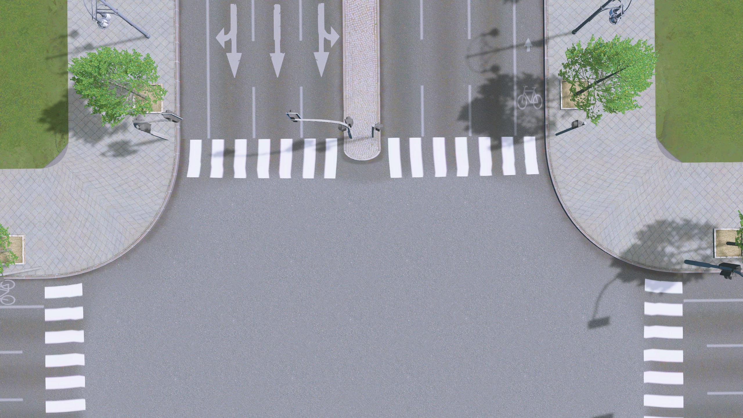
So this looks great already.

Textures like to jump, I already tested that when the street editor was new.

You can only prevent texture mirroring by using Vertex Paint, but I haven't done it 100% yet.

What you want to do, give the texture a depth that you can see the cobblestones in between, now there are certainly different ways.

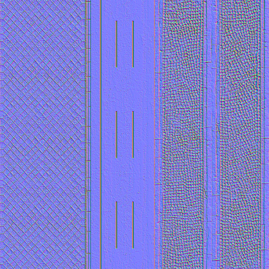
Either search the internet for a free texture that has a normal map and a specular map or do everything yourself.

Doing it yourself is a bit more complicated, you create different cubes with a high division, which randomly crumple the points of the object, so that it looks uneven.

From the templates then again and again copies, better instances, create and then arrange as desired.

Create the spaces between the cobblestones with the help of a layer, subdivide this layer and crumple it by chance, position the layer so that the cobblestones look out over it.

The whole thing just miss a texture for the cobblestones, also here the highlights you wanted to combine suitably with noise texture and object surface.

When everything is ready you have to create a texture from this object, the procedure is called texture baking, thereby various textures are created from the object, for this you use a low-poly object, or just a flat layer and cover the object with the cobblestone.

As far as texture baking is concerned, there are plenty of tutorials on the internet.

There is also a great addon for blender called "TexTools for Blender" which includes 18 different texture baking options and much more.
https://blenderartists.org/t/textools-for-blender/700811

Translated with www.DeepL.com/Translator
 
Thx for the tips. I spent yesterday fighting with the nodes over the zebra stripes. If I would paint their vertices, they would shrink and compress too small, and if I let them scroll, then they "wobble" or get "jagged" (they don't look straight). I even changed the geometry around but nothing that I did would fix the problem. This was as close as I could get and I'm not happy at all:
20180910001148-1.jpg


As for the normalmapping, I understand how to bake but I definitely don't want to model every cobblestone. I was thinking more of sending a simple heightmap based on the texture image into normalmap-online so that the dark parts (around the stones) look a bit deeper. I read somewhere that I think the red channel is not reversed or something or that normalmaps don't have much an effect on roads? I'm just wondering if I should even try doing it or if it would be another huge waste of time.
 
As far as the nodes are concerned, nodes are compressed by half and then bent from the center to the other street.

The left half to the left and the other half to the right.

There must be no further mesh subdivision between the middle lane and the kerbstone, otherwise there will be display errors.

In this area no macantam texture details may be, the further a pattern reaches from the beginning of a node to the end the further the texture is bent outwards.

Translated with www.DeepL.com/Translator
 
Hm strange, the in-game streets themselves have normal maps too, so it should work.
The normal map must end with _n at the end of the filename.
Example: Street_n.jpg or Street_n.png
 
I never noticed normalmaps on the vanilla roads. Do they really have them? Which ones?

I'm having real trouble with the normalmap. It seems like I need to invert the green channel on the parts of the mesh that get tiled (non-painted verts), but then not for faces with painted verts. It's giving me a head-ache. :(
 
I have already exported several Vanilla streets with textures and all have a normal map.

Will test it again tonight or tomorrow.

There are two different normal maps but this has to do with the game engine, there are different game engines and some use a different normal map.

But mine is that the normal maps from Blender are the same ones used by the Unity engine.
 
As far as i know you always have to invert the red channel of the normal map when creating things for Unity. For Unreal engine you would have to invert the green channel.

This is because of the different coordinate systems. In Blender Z-axis is up, while in Unity it represents the depth and Y is up.
 
A good starting point, but when creating an object in Blender, you should rotate the local object axis so that the Z-axis is the depth axis and so in Blender the Y-axis becomes the vertical axis.
But I will take a closer look at this
 
Well, you guys are gonna love this one ... turns out that you need to invert part of the normal map and not the other part. Ugh.

1. For road mesh faces where you paint the vertices magenta to prevent scrolling, you DO NOT invert the normal map.
2. For unpainted faces, you INVERT THE GREEN channel on the normal map.

Proof is in the pudding. Notice the difference in normal map curb edges vs. median edges. This was the only way I could get everything to be consistent in-game.
strasse-17-juni_n.png.cbdd14c62e03ca78381d4a1697cb7204.png

result:
20180914031305_1.jpg.95d6edf179dc31e14eb71e6c8970434f.jpg


vert-paint.thumb.jpg.dc97faa052b9b3359b2c1bf7d7853eef.jpg
 
So I did quite a simple test, in the normal map which was calculated out of Blender, there is no red channel, inverting the red channel has no effect, because the red channel in my example contains neutral-gray.
What I can confirm, however, is that the normal map is only evaluated with the bridge shader, with the basic shader a normal map is without function.
Test-Segment_n.png
 
Looks totally awesome.
That's totally misleading, there's nothing about that in the Cities Wiki, or did I miss it?
Areas where scrolling is prevented don't have to be inverted, so normally you have to invert the green channel?
Ok I found out how to get Blender to calculate the correct normal map.

Under Bake you need the following setting:

Swizzle: +X +Y +Z change to +X -Z +Y

But it doesn't help much if you have to invert the normal map at certain places in the green channel.

But you have to use the bridge shader explicitly, with the basic shader no normal map is evaluated.

Well, at least I have some new experience and can use it for my tutorial/manual about the street editor.

Don't be disappointed, unfortunately it will only be in German version.

Translated with www.DeepL.com/Translator
 
A good starting point, but when creating an object in Blender, you should rotate the local object axis so that the Z-axis is the depth axis and so in Blender the Y-axis becomes the vertical axis.
I'd do that when exporting fbx but maybe i'm missing something?

Sorry for confusion about the red channel. Didn't know it's the green one when talking about roads. So confusing, but that's how the shaders work, i guess. :confused:

Very interesting topic and worth to be implemented in the wiki.
The street looks really pretty!

Thank you guys.
 
So I know about the local axis in Blender and always do it like this.

Create a plane, then press R for Rotate and then X for the X axis, then enter 90 and the object will be rotated 90 degrees.

Now you go into the edit mode and press R again and then X and enter -90 as the value.

If you leave the edit mode again and set the axes view from global to local, you will see that the Z-Acnse now points into space and the Y-axis upwards.

Export to FBX you have to set Forward to -Z Forward and Up to Y Up.

For shell, enter 100, this value is also entered in the Street Editor when importing under shell.

Translated with www.DeepL.com/Translator
 
Which way it points, as far as I know, doesn't matter.

What is absolutely important with nodes is that between the centerline and the outside edge (sidewalk) no further points may be at the end of a node.

If there are more points at the end of a node, then there will be some misrepresentations at the nodes, you can see bluish spaces between them.

Your upper picture is just as correct as the lower picture.

Upper picture, here the left diagonal runs to the node-centre end and the right diagonal comes from the centre and runs outwards to the node-end.

Lower picture, left diagonal runs from the outside edge to the node center end and the right diagonal (red) runs from the node center end to the outside edge.

By outside edge I mean the edge of the road from where the sidewalk begins.

I am working myself with the street editor for my tutorial/manual, which deals very exactly with segments and nodes, what has to be considered.

Translated with www.DeepL.com/Translator
 
B1.jpg B2.jpg
Picture 1 and 2 are correct

B3.jpg
In picture 3 a few points are marked, the white point is important and always forms the middle, therefore there must always be a subdivision in the middle.

The two points marked yellowish in the picture, which must not exist at the end of a node, cause display errors at intersections of streets.